產(chǎn)品中心
美國(guó)強(qiáng)鹿柴油機(jī)維修配件技術(shù)中心
約翰迪爾John Deere柴油機(jī)配件 美國(guó)麥克福斯
卡特彼勒柴油發(fā)動(dòng)機(jī)參數(shù)
沃爾沃發(fā)動(dòng)機(jī)全系參數(shù)
英國(guó)珀金斯原廠配件
珀金斯柴油機(jī)技術(shù)中心
珀金斯發(fā)動(dòng)機(jī)零件查詢圖冊(cè)
日本三菱柴油機(jī)發(fā)電機(jī)配件
德國(guó)道依茨 韓國(guó)大宇柴油發(fā)動(dòng)機(jī)配件
康明斯全系列柴油發(fā)動(dòng)機(jī)
沃爾沃 MTU 原廠配件銷售中心
瑞典沃爾沃遍達(dá)原裝柴油機(jī)配件
康明斯維修技術(shù)中心
卡特彼勒柴油發(fā)動(dòng)機(jī)原廠配件銷售中心
品牌柴油發(fā)電機(jī)組
康明斯柴油發(fā)動(dòng)機(jī)配件中心
約翰迪爾強(qiáng)鹿六缸柴油機(jī)低壓燃油系統(tǒng)流程操作圖迪爾904 1054 1204拖拉機(jī)操作手冊(cè)

約翰迪爾強(qiáng)鹿六缸柴油機(jī)低壓燃油系統(tǒng)流程操作圖迪爾904 1054 1204拖拉機(jī)操作手冊(cè)
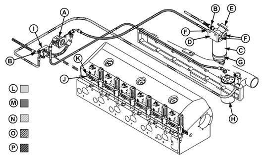
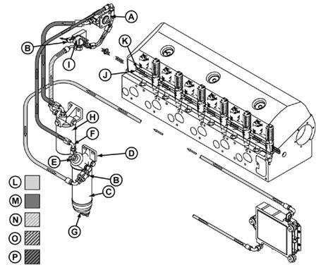
Low Pressure Dual Rail Fuel Supply System Operation
A—Fuel Transfer Pump E—Hand Primer Pump I—Fuel Manifold M—Primary-Filtered Fuel
B—In-line Check Valves F—Primary Filter Base Outlets J—Fuel Supply Rail N—Final-Filtered Fuel
C—Primary Filter G—Water Separator Bowl K—Fuel Return Rail O—Recirculated Fuel
D—Primary Filter Base H—Final Filter L—Suction Fuel from Tank P—Return-to-Tank Fuel

The fuel transfer pump (A) draws fuel from the fuel passages to route fuel into and out of the cylinder tank through an in-line check valve (B) into the primary head. On some applications, the fuel manifold also filter base (D) contains a hand-primer pump (E) and contains a fuel pressure sensing switch. The fuel three outlet passages (F). The water separator bowl pressure regulator will maintain fuel pressure at 410– (G), which screws to the bottom of the fuel filter base. 480 kPa (4.1–4.8 Bar) (60–70 psi).
A self venting drain valve is mounted on the bottom of
the clear bowl. Fuel flows from the fuel manifold into the fuel supply rail in the cylinder head. Fuel rails are drilled passages
Fuel flows from one of the primary filter base outlets to in the cylinder head that route fuel to each unit
the inlet of the fuel transfer pump mounted on the rear injector. The fuel supply rail (J) is the bottom drilled
of the head. The fuel transfer pump is a gear type passage; the return fuel rail (K) is the top drilled
pump. The pump shaft is coupled to the end of the passage. The two passages are connected at the front camshaft. The fuel transfer pump contains a pressure of the head.
regulating valve for system over-pressure protection. A
bypass valve in the pump base allows fuel to bypass Excess fuel not needed by the electronic unit injectors the gears during hand priming. flows from the cylinder head into the fuel manifold. The
fuel flows past the fuel temperature sensor. At this Fuel flows from the outlet of the fuel transfer pump to point the fuel is routed in one of two directions. The the inlet of the final fuel filter (H). The spin-on final return to tank orifice will cause approximately 10% of filter is the last clean-up of the fuel before entering the the fuel to flow back to the fuel tank. The return-to-tank engine. fuel enters the tank at the bottom to prevent fuel
drain-back. The remaining 90% of the fuel will flow Fuel flows from the outlet of the final filter to the fuel past the pressure regulating valve and return to the manifold (I) mounted on the rear of the cylinder head. inlet of the fuel transfer pump to be recirculated The fuel manifold contains a fuel temperature sensor, through the cylinder head.
pressure regulating valve, return to tank orifice, and
RG,RG34710,1525 –19–30SEP97–2/2


