
約翰迪爾John Deere柴油機連桿和蓋磨損或損壞的根本原因
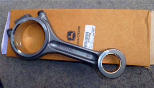
約翰迪爾John Deere柴油機連桿和蓋磨損或損壞的根本原因
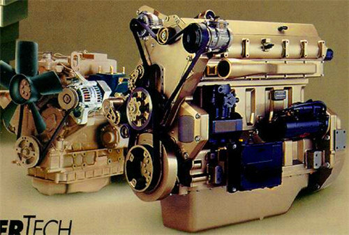
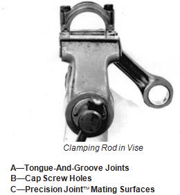
1.檢查迪爾John Deere柴油機連桿和蓋是否磨損或損壞,如接頭區域(A)中的碎屑或刻痕。
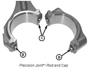
重要事項:不要劃傷連桿和蓋的接合面。這對于精密接頭非常關鍵 確保正確就位的連桿。切勿用鋼絲刷或其他工具刮擦接合面(C);必須保留互鎖配合面。
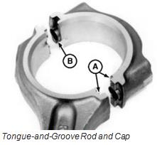
2.檢查迪爾John Deere柴油機蓋上的帶帽螺釘孔(B)及其周圍。如果發現任何缺陷,更換連桿和蓋。
重要事項:如果更換連桿,請使用相同類型的接頭設計。不要混合使用精密接頭 連桿以及同一強鹿約翰迪爾John Deere柴油發動機上的榫槽連桿。有關建議,請參見零件目錄。
3.小心地將迪爾John Deere柴油機連桿夾在軟口臺鉗中(蓋端朝上)。
4.安裝不帶軸承的蓋。
重要事項:檢查連桿孔內徑時,切勿使用新的連桿帶帽螺釘。僅在連桿的最終裝配時使用新的帶帽螺釘。
5.在榫槽連桿上:首先擰緊盲孔帶帽螺釘,然后將開孔帶帽螺栓擰緊至以下規格。
規格
榫槽連接
連桿帶帽螺釘初始扭矩……27牛頓·米(20磅-英尺)接下來,將連桿帶帽螺釘擰緊至以下規格。
榫槽連桿和帽
精密接頭 連桿和帽
虎鉗中的夾緊連桿
A型榫槽接頭B型帶帽螺釘孔C型精密接頭 配合面規格
榫槽連接
連桿帶帽螺釘最終扭矩…75牛頓·米(55磅-英尺)加上90–100
順時針轉動
參見扭轉連桿蓋
螺釘,將在本組后面介紹。
6.關于精密接頭迪爾John Deere柴油機連桿:首先擰緊最靠近活塞端的連桿帶帽螺釘,然后將其他帶帽螺釘擰緊至以下規格。
規格
精密接頭 連桿
帶帽螺釘扭矩……95牛頓·米(71磅-英尺)加上90–100
順時針轉動
參見扭轉連桿蓋
螺釘,將在本組后面介紹。
精密接頭是迪爾公司DPSG的商標,OUO1004884–19–08JUN99–2/4
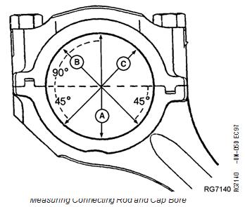
7.使用內徑千分尺,測量孔中心的連桿孔,并記錄測量值,如下所示:
•與連桿/蓋接頭(A)成直角。
•測量步驟“A”(B)左側。
•測量步驟“A”(C)的右側。
規格
連桿孔(無軸承)-內徑…81.051-81.077 mm(3.191-3.192英寸)
8.比較測量值。如果最大和最小測量值之間的差值大于0.04 mm(0.0016英寸),連桿和蓋不圓。更換測量連桿和蓋孔連桿和蓋。
規格
連桿孔最大值不圓度……0.025毫米(0.0010英寸)
7.使用內徑千分尺,測量孔中心的連桿孔,并記錄測量值,如下所示:
•與連桿/蓋接頭(A)成直角。
• 測量步驟“A”(B)左側。
• 測量步驟“A”(C)的右側。
規格
連桿孔(無軸承)-內徑…81.051-81.077 mm(3.191-3.192英寸)
8.比較測量值。如果最大和最小測量值之間的差值大于0.04 mm(0.0016英寸),連桿和蓋不圓。更換測量連桿和蓋孔
連桿和蓋。
規格
連桿孔最大值不圓…0.025毫米(0.0010英寸)
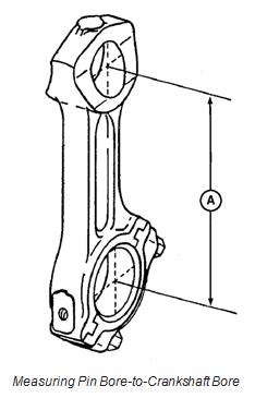
9.測量活塞連桿活塞銷孔到曲軸孔的中心到中心尺寸(A),并與給出的規格進行比較。如果測量值不在規格范圍內,則更換連桿。
規格
活塞銷孔到曲軸孔的中心線-尺寸……222.20-222.30 mm(8.748-8.752英寸)
A-中心到中心尺寸
檢查活塞銷和襯套
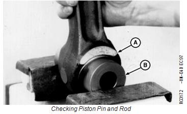
1.將活塞銷(B)插入活塞銷襯套,并小心地夾在軟口虎鉗中。
2.前后旋轉連桿(A)數次,以確保連桿在活塞銷上自由移動。
3.從連桿上拆下活塞銷。
A-連桿檢查活塞銷和連桿
B活塞銷
4.從連桿襯套的任一側插入銷。如果銷的一端是自由的,但另一端是緊密的,則孔可以是錐形的(A)。如果銷釘從兩側自由進入,但在中心處擰緊,則孔為喇叭口(B)。
5測量連桿銷襯套內徑和活塞銷外徑。將測量值與下面給出的規格進行比較:
Inspect Rod and Cap
1. Inspect rod and cap for wear or damage, such as chips or nicks in the joint areas (A).
IMPORTANT: Do not nick the joint surfaces of rod and cap. This is very critical on Precision Joint rods to assure proper seating. Never scrape joint surfaces (C) with a wire brush or other tool; the interlocking mating surfaces must be preserved.
2. Inspect in and around cap screw holes (B) in cap. If any defects are found, replace rod and cap.
IMPORTANT: If replacing a connecting rod, use the same type of joint design. Do Not intermix Precision Joint rods and tongue-and-groove rods on the same engine. See parts catalog for recommendations.
3. Carefully clamp rod in a soft-jawed vise (cap end upward).
4. Install cap WITHOUT bearing.
IMPORTANT: Never use new connecting rod cap screws when checking rod bore I.D. Use new cap screws only for final assembly of connecting rods.
5. On tongue-and-groove connecting rods: Initially tighten blind-hole cap screw, then, tighten open-hole cap screw to the following specifications.
Specification
Tongue-and-Groove Connecting
Rod Cap Screw—Initial Torque...... 27 N•m (20 lb-ft)
Next, tighten rod cap screws to the following specifications.
Tongue-and-Groove Rod and Cap
Precision Joint Rod and Cap
Clamping Rod in , Vise
A—Tongue-And-Groove Joints B—Cap Screw Holes
C—Precision Joint Mating Surfaces
Specification
Tongue-and-Groove Connecting
Rod Cap Screw—Final Torque ... 75 N•m (55 lb-ft) plus 90–100
turn clockwise
See TORQUE-TURN CONNECTING ROD CAP
SCREWS, described later in this group.
6. On Precision Joint connecting rods: Initially tighten rod cap screw closest to piston end, then tighten other cap screw to the following specifications.
Specification
Precision Joint Connecting Rod
Cap Screw—Torque ...... 95 N•m (71 lb-ft) plus 90–100
turn clockwise
See TORQUE-TURN CONNECTING ROD CAP
SCREWS , described later in this group.
Precision Joint is a trademark of Deere & Company DPSG,OUO1004,884 –19–08JUN99–2/4
7. Using an inside micrometer, measure rod bore at center of bore and record measurements as follows:
• At right angle to rod/cap joint (A).
• At 45 left of measurement step “A” (B).
• At 45 right of measurement step “A” (C).
Specification
Connecting Rod Bore (Without
Bearings)—ID .... 81.051—81.077 mm
(3.191—3.192 in.)
8. Compare the measurements. If difference between the greatest and least measurement is more than 0.04 mm
(0.0016 in.), the rod and cap are out-of-round. Replace Measuring Connecting Rod and Cap Bore
both connecting rod and cap.
Specification
Connecting Rod Bore—Maximum
Out-of-Round ...... 0.025 mm (0.0010 in.)
7. Using an inside micrometer, measure rod bore at center of bore and record measurements as follows:
• At right angle to rod/cap joint (A).
• At 45 left of measurement step “A” (B).
• At 45 right of measurement step “A” (C).
Specification
Connecting Rod Bore (Without
Bearings)—ID ..... 81.051—81.077 mm
(3.191—3.192 in.)
8. Compare the measurements. If difference between the greatest and least measurement is more than 0.04 mm
(0.0016 in.), the rod and cap are out-of-round. Replace Measuring Connecting Rod and Cap Bore
both connecting rod and cap.
Specification
Connecting Rod Bore—Maximum
Out-of-Round ..... 0.025 mm (0.0010 in.)
9. Measure rod’s piston pin bore-to-crankshaft bore center-to-center dimension (A) and compare with specification given. If measurement is not within specification, replace rod.
Specification
Centerline of Piston Pin Bore-to-Crankshaft Bore—
Dimension...... 222.20—222.30 mm
(8.748—8.752 in.)
A—Center-to-Center Dimension
Inspect Piston Pins and Bushings
1. Insert piston pin (B) through piston pin bushing and carefully clamp in a soft-jawed vise.
2. Rotate connecting rod (A) back and forth several times to make sure connecting rod moves freely on piston pin.
3. Remove piston pin from connecting rod.
A—Connecting Rod Checking Piston Pin and Rod
B—Piston Pin
4. Insert pin from either side of rod bushing. If pin is free on one end, but tight on the other, the bore could be tapered (A). If pin enters freely from both sides, but is tight in the center, bore is bell-mouthed (B).
5Measure I.D. of rod pin bushing and O.D. of piston pin. Compare measurements with specifications given below:
Specification
Piston Pin—OD .... 47.597—47.613 mm
(1.8739—1.8745 in.) Piston Pin Bore in Piston—ID .... 47.620—47.630 mm
(1.8748—1.8752 in.)
Installed Connecting Rod Pin
Bushing (After Boring)—ID.... 47.655—47.681 mm
(1.8762—1.8772 in.)
Connecting Rod Pin-to-Bushing—
Oil Clearance...... 0.042—0.084 mm
(0.0017—0.0033 in.) Wear Limit ....... 0.102 mm (0.0040 in.)
6. If necessary, remove and replace piston pin bushing. See REMOVE PISTON PIN BUSHING, CLEAN AND INSPECT PIN BORE, later in this group.
頂部裝入式油過濾器裝配包含過濾器和油調節閥。 此新型設計裝配還包含一個回排閥,卸下油過濾器頂部的蓋就會開啟此閥。松開蓋之后等待30秒,油就會回排以防止油噴濺。 此蓋是塑料的,而殼體是鋁的,高雄Perkins帕金斯1106D-E70TAG2柴油機上門維修電話多少錢,宜昌Perkins帕金斯4008TAG1A強鹿約翰迪爾John Deere柴油發動機多小錢費用報價單,吳忠Perkins帕金斯1104D-E44TA強鹿約翰迪爾John Deere柴油發動機缸蓋中心,巴音郭楞大修包珀金斯1106強鹿約翰迪爾John Deere柴油發動機哪家好,興安Perkins帕金斯1204F-E44TTAG2強鹿約翰迪爾John Deere柴油發動機上下大修包代理商,新竹Perkins帕金斯4008TAG強鹿約翰迪爾John Deere柴油發動機銷售售后代理商在什么地方買,白山Perkins帕金斯402D-05G強鹿約翰迪爾John Deere柴油發動機缸套組件費用報價單,所以在拆卸和安裝此蓋時特別注意不要刮剝它。如果使用的工具不合適或應用的扭矩過大,則可能會損壞蓋的扭轉面。請使用 32 毫米(1-1/4 英寸)的扳手拆卸和安裝此蓋。安裝蓋時,扭矩范圍為40至50 牛·米(30-37 磅英尺)。新的過濾器介質能夠使強鹿約翰迪爾John Deere柴油發動機在符合特定條件時使用500小時的換油間隔。有關詳細信息,請參見《操作、保養和維修指南》(OMRG-36864)。
合伙人(甲方):
姓名:
身份證號:
住址:
合伙人(乙方):
姓名:
身份證號:
住址:
經甲乙雙方充分協商,就合伙從事美容瘦身經營一事,自愿達成如下協議,以資信守:
第一條 合伙宗旨:共同合作、合法經營、利益共享、風險共擔;
第二條 合伙名稱 :_________________
經營地址:
第三條 合伙經營項目和范圍:__________________
第四條 合伙期限暫定五年,自本合伙協議簽訂之日起計算。合伙期限屆滿,經各合伙人協商一致可以續展延長經營期限,也可以根據市場情況提前終止合伙經營。提前終止合伙或者延長合伙經營應須提前六個月取得各合伙人的一致意見,在期滿前辦理完畢有關手續。
第五條 出資金額、 方式、期限。
(一)甲方以現金方式出資 元,乙方以現金方式出資 元 ,甲乙雙方各占投資總額的50%
(二)合伙人的出資,于___年__月__日以前交齊。
(三)本合伙出資各占投資總額的50%,作為確定盈余分配和債務承擔的基礎。
(四)合伙期間各合伙人的出資為共有財產,不得隨意請求分割。合伙終止后,各合伙人的出資仍為個人所有,屆時予以返還。
第六條:合伙人的分工、權利與義務
(一)甲乙協商一致共同推舉甲方作為合伙負責人,全面負責合伙業務的日常經營與管理,包括對職工的管理、培訓,考勤、客戶協調,業務開拓等事宜,并享有每月 元的工資待遇。
(二)乙方享有對財物賬目的監督權利,對于涉及財務、賬目以及借款、還款、日常投資等資金使用事項在超過 元額度( 元以下的應各自記賬留存憑證定期對賬),應須甲乙雙方協商一致方可進行。
第七條 盈余分配與債務承擔。
合伙各方共同經營、共同合作,共擔風險,共負盈虧。
(一)盈余分配:扣除店里的水、電、暖、氣、租金、職工工資、稅金等日常經營費用,剩余的按雙方的投資比例分配(即每人一半,平均分配),予每月5日前結算上一月的賬目,進行盈余分配。
(二)債務承擔:合伙債務先以合伙財產償還,合伙財產不足清償時,由各合伙人按投資比例分擔,任何一方對外償還后,另一方應當按比例在10日內向對方清償自己應負擔的部分。
第八條:違約責任:
(一) 合伙人未經其他合伙人一致同意而轉讓其財產份額的,
如果他合伙人不愿接納受讓人為新的合伙人,可按退伙處理,轉讓人應賠償其他合伙人因此而造成的損失。
(二) 合伙人違反本協議導致合伙損失的,應當對其他合伙人承擔
賠償責任
第九條:經協商一致,合伙人可以修改本協議或對未盡事宜進行補充;補充、修改內容與本協議相沖突的,以補充、修改后的內容為準。
第十條:合同爭議解決方式。
凡因本協議或與本協議有關的一切爭議,合伙人之間共同協商,如協商不成,可在邢臺市橋西區人民法院起訴。
第十一條:本合同一式___份,合伙人各執一份。本合同經全體合伙人簽名、蓋章后生效。
合伙人(甲方):
合伙人(乙方):
年 月 日
年 月 日
