
產(chǎn)品中心
美國強(qiáng)鹿柴油機(jī)維修配件技術(shù)中心
約翰迪爾John Deere柴油機(jī)配件 美國麥克福斯
卡特彼勒柴油發(fā)動(dòng)機(jī)參數(shù)
沃爾沃發(fā)動(dòng)機(jī)全系參數(shù)
英國珀金斯原廠配件
珀金斯柴油機(jī)技術(shù)中心
珀金斯發(fā)動(dòng)機(jī)零件查詢圖冊
日本三菱柴油機(jī)發(fā)電機(jī)配件
德國道依茨 韓國大宇柴油發(fā)動(dòng)機(jī)配件
康明斯全系列柴油發(fā)動(dòng)機(jī)
沃爾沃 MTU 原廠配件銷售中心
瑞典沃爾沃遍達(dá)原裝柴油機(jī)配件
康明斯維修技術(shù)中心
卡特彼勒柴油發(fā)動(dòng)機(jī)原廠配件銷售中心
品牌柴油發(fā)電機(jī)組
康明斯柴油發(fā)動(dòng)機(jī)配件中心
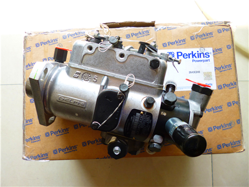
Perkins珀金斯900 3.152柴油發(fā)動(dòng)機(jī)2643 B134燃料噴射泵
詳細(xì)描述
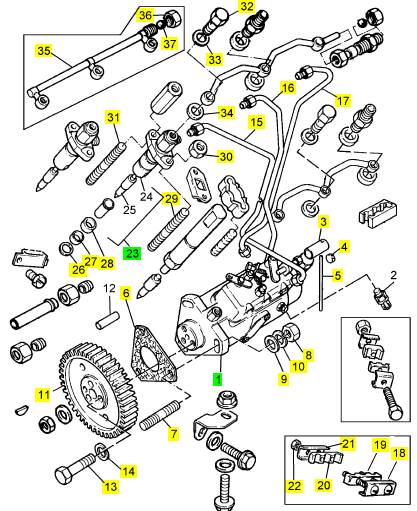
項(xiàng)目 零配件號(hào)碼 最新件號(hào) 描述
1 2643 B134 1 2643 B134 燃料噴射泵
3 3281 M002 1 3281 M002 套筒
4 31718104 1 31718104 密封
5 31718105 1 31718105 金屬線
6 33828112 1 3682 A008 密合墊 - 燃料的 INJ 泵
7 2217575 3 2217575 圖釘
8 0576002 3 0576002 螺帽
9 0920003 3 0920003 墊圈
10 0920053 3 0920053 墊圈
11 41115379 1 41115379 噴射泵傳動(dòng)機(jī)構(gòu)
11 0350010 1 0350010 合釘
11 1 燃料噴射泵傳動(dòng)機(jī)構(gòu)
13 0746214 3 0746214 螺旋
14 0920053 3 0920053 墊圈
15 3521 E018 1 3521 E018 燃料噴射管 號(hào)碼1 CYL。
16 3521 E019 1 3521 E019 燃料噴射管 號(hào)碼2 CYL。
17 3521 E021 1 3521 E021 燃料噴射管 號(hào)碼3 CYL。
18 38631117 1 38631117 板
19 36845115 1 36845115 夾
20 36845115 1 36845115 夾
21 36511127 1 36511127 板
22 2211401 2 2211401 螺帽
23 2645630 3 2645630 噴油器
(23) 2645630 R 3 2645630 R 噴油器 -交換
26 0921173 3 0921173 噴油器墊圈
27 33813127 3 3311 A041 密封 -噴油器
28 33813126 3 33813126 間隔器
29 2216105 3 2216105 圖釘
30 0576002 6 0576002 螺帽
31 2216105 3 2216105 圖釘
32 3218 R039 3 3218 R039 班卓琴螺拴
32 0095315 3 0095315 班卓琴螺拴 U186029K
33 2411 D007 3 2411 D007 墊圈
33 0921176 3 0921176 墊圈 U186029K
34 2411 D007 3 2411 D007 墊圈
34 0921176 3 0921176 墊圈 U186029K
35 35587359 1 35587359 回油管
36 0576111 1 0576111 螺帽
37 0020006 1 0020006 球
|
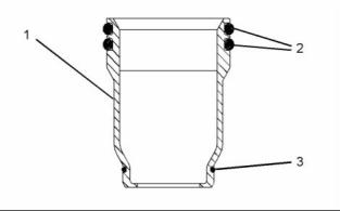
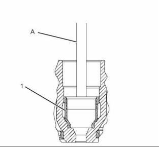
4. Tighten the nut on Tooling (A) until electronic unit injector sleeve (1) is pulled free from the cylinder head. |
|
g01043165 |
|
Illustration 17 |
|
g01393881 |
|
Illustration 16 |
|
5. Remove O-ring seals (2) and O-ring seal (3) from electronic unit injector sleeve (1). |
|
i02754766 Electronic Unit Injector Sleeve - Install |
|
Installation Procedure |
|
Table 5 |
|
Required Tools |
|
Tool |
|
Part Number GE50021 GE50023 GE50024 GE50022 CV60893 |
|
Part Description Injector Sleeve Tool Tapered Brush |
|
Qty 1 |
|
g01393891 |
|
Illustration 18 |
|
A |
|
1 |
|
2. Install new O-ring seals (2) and (3) to electronic unit injector sleeve (1). |
|
B C |
|
Small Bore Brush End Brush |
|
1 |
|
1 |
|
3. Install electronic unit injector sleeve (1) to Tooling (A). |
|
Retaining Compound |
|
1 |
|
4. Apply a small continuous bead of Tooling (C) to |
|
NOTICE |
|
surface (X) of electronic unit injector sleeve (1). |
|
Keep all parts clean from contaminants. |
|
5. Lubricate O-ring seals (2) with clean engine oil. |
|
Contaminants may cause rapid wear and shortened component life. |
|
6. Position electronic unit injector sleeve (1) and Tooling (A) in the cylinder head. Use care not to damage O-ring seals (2) and (3). |
|
1. Use Tooling (B) to clean the bore in the cylinder |
|
head for the electronic unit injector sleeve. |
|
7. Use Tooling (A) and a soft faced hammer to install electronic unit injector sleeve (1) to the cylinder head. |
|
NOTICE |
|
Ensure that the electronic unit injector sleeve and the cylinder head bore are completely free of oil, dirt, and sealant debris. |
|
Note: Ensure that the electronic unit injector sleeve is properly seated in the cylinder head. |
|
This document has been printed from SPI². Not for Resale |
![]()
![]()
![]()
![]()
![]()
![]()
![]()

![]()
|
KENR6906 |
|
13 Disassembly and Assembly Section |
|
8. Install the electronic unit injectors. Refer to Disassembly and Assembly, “Electronic Unit Injector - Install”. |
|
Installation Procedure |
|
9. Fill the cooling system with coolant. Refer to Operation and Maintenance, “Cooling System Coolant - Change”. |
|
i02754770 |
|
Air Cleaner - Remove and Install |
|
g01380888 |
|
Removal Procedure |
|
Illustration 20 |
|
Typical example |
|
NOTICE Keep all parts clean from contaminants. |
|
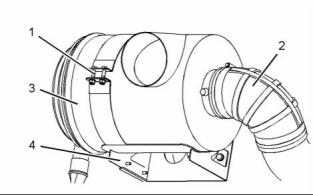
1. If necessary, position mounting bracket (4) on the cylinder head and install the bolts that secure the mounting bracket. Tighten theM12 bolts to a torque of 100 N·m (74 lb ft). Tighten the 3/8" bolts to a torque of 47 N·m (35 lb ft). |
|
Contaminants may cause rapid wear and shortened component life. |
|
2. Position air cleaner (3) on mounting bracket (4). Ensure the correct orientation of the air cleaner. |
|
3. Install fasteners (1). Tighten the fasteners to a torque of 55 N·m (41 lb ft). |
|
4. Connect hose (2) and tighten the hose clamp securely. |
|
i02754771 |
|
Turbocharger - Remove |
|
g01380888 |
|
Illustration 19 |
|
Typical example |
|
Removal Procedure |
|
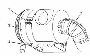
1. Loosen the hose clamp and disconnect hose (2). |
|
Start By: |
|
2. Remove fasteners (1) and remove air cleaner (3) from mounting bracket (4). Note the orientation of the air cleaner. |
|
a. Remove the exhaust elbow. Refer to Disassembly and Assembly, “Exhaust Elbow - Remove and Install”. |
|
3. If necessary, remove the bolts that secure mounting bracket (4) and remove the mounting bracket. |
|
NOTICE |
|
Care must be taken to ensure that fluids are contained during performance of inspection, maintenance, test- ing, adjusting and repair of the product. Be prepared to collect the fluid with suitable containers before open- ing any compartment or disassembling any compo- nent containing fluids. |
|
Dispose of all fluids according to local regulations and mandates. |
|
This document has been printed from SPI². Not for Resale |
![]()
![]()
![]()
![]()
![]()
![]()
![]()
|
14 |
|
KENR6906 |
|
Disassembly and Assembly Section |
|
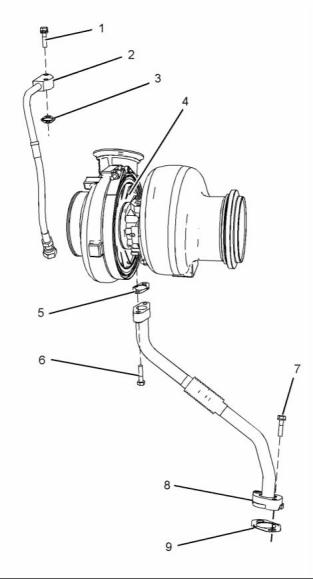
c. Remove tube assembly (2) and joint (3) from |
|
turbocharger (4). |
|
NOTICE |
|
Keep all parts clean from contaminants. |
|
3. Follow Steps 3 through 3.c in order to remove the |
|
tube assembly for the oil drain to the turbocharger. |
|
Contaminants may cause rapid wear and shortened component life. |
|
a. Remove bolts (6) and (7). b. Remove tube assembly (8). c. Remove joints (5) and (9). |
|
1. Disconnect the air hoses from the turbocharger inlet and from the turbocharger outlet. |
|
4. Attach a suitable lifting device to turbocharger (4). The weight of the turbocharger is approximately 32 kg (71 lb). |
|
g01382805 |
|
Illustration 22 |
|
Typical example |
|
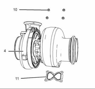
5. Remove nuts (10). Use the lifting device to remove turbocharger (4) from the exhaust manifold. |
|
6. Remove gasket (11). |
|
i02754772 |
|
Turbocharger - Install |
|
g01380889 |
|
Illustration 21 |
|
Installation Procedure |
|
Typical example |
|
Table 6 |
|
2. Follow Steps 2.a through 2.c in order to remove the |
|
Required Tools Part |
|
tube assembly for the oil feed to the turbocharger. |
|
a. Disconnect tube assembly (2) from the engine oil filter base. |
|
Tool |
|
Number |
|
Part Description |
|
Qty |
|
A |
|
CV60889 |
|
Anti-Seize Compound |
|
1 |
|
b. Remove bolts (1). |
|
This document has been printed from SPI². Not for Resale |
![]()
![]()
![]()
![]()
![]()

|
KENR6906 |
|
15 Disassembly and Assembly Section |
|
NOTICE Keep all parts clean from contaminants. |
|
Contaminants may cause rapid wear and shortened component life. |
|
1. Ensure that all mating surfaces are clean and free from damage. |
|
g01382805 |
|
Illustration 23 |
|
Typical example |
|
2. Position a new gasket (11) on the exhaust manifold. |
|
3. Attach a suitable lifting device to turbocharger (4). The weight of turbocharger is approximately 32 kg (71 lb). Use the lifting device to install the turbocharger to the exhaust manifold. |
|
g01413397 |
|
Illustration 24 |
|
4. Apply Tooling (A) to the threads of the exhaust |
|
Typical example |
|
manifold studs. |
|
6. Follow Steps 6.a through 6.c in order to install the |
|
tube assembly for the oil drain to the turbocharger. |
|
5. Install nuts (10). Tighten the nuts to a torque of |
|
55 N·m (41 lb ft). |
|
a. Place a new joint (9) and tube assembly (8) in position and install bolts (7) finger tight. |
|
If a new turbocharger is installed, loosen the V-band clamps and rotate the bearing housing and the compressor housing to the correct positions. |
|
b. Position a new joint (5) between turbocharger (4) and tube assembly (8). Install bolts (6) finger tight. |
|
c. Tighten bolts (6) and (7) to a torque of 28 N·m (21 lb ft). |
|
7. Lubricate the bearings of turbocharger (4) with clean engine oil through oil inlet port (X). Rotate the shaft of the turbocharger in order to distribute the lubricant. |
|
This document has been printed from SPI². Not for Resale |
