
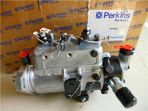
Perkins珀金斯1506A柴油發動機T400727燃油噴射泵
詳細描述
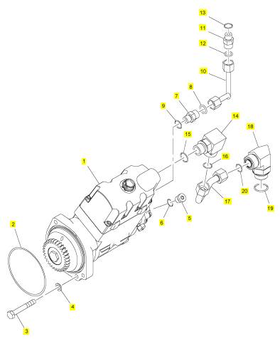
項目 零配件號碼 新件號 描述
1 T400727 1 T400727 燃油噴射泵
2 T400733 1 T400733 密封O型圈
3 CH11830 2 CH11830 公制的螺拴
4 CH11819 2 CH11819 墊圈
5 T400427 1 T400427 栓塞
6 CH11880 1 CH11880 密封O型圈
7 T407241 1 T407241 連接器
8 T408416 1 T408416 密封O型圈
9 CH11880 1 CH11880 密封O型圈
10 T400732 1 T400732 管
11 T407241 1 T407241 連接器
12 T408416 1 T408416 密封O型圈
13 CH11880 1 CH11880 密封O型圈
14 T400734 1 T400734 承接器
15 T400188 1 T400188 密封O型圈
16 T416678 1 T416678 密封O型圈
17 T400729 1 T400729 管
18 T400728 1 T400728 承接器
19 T400248 1 T400248 密封O型圈
20 T416678 1 T416678 密封O型圈
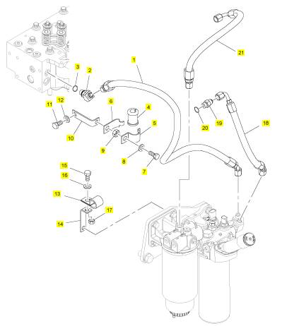
項目 零配件號碼 新件號 描述
1 T400654 1 T400654 燃油管
2 T400646 1 T400646 承接器
3 CH11880 1 CH11880 密封O型圈
4 T400660 1 T400660 襯套
5 T400659 1 T400659 托架
6 T400658 1 T400658 托架
7 T405199 1 T405199 螺旋
8 T405615 2 T405615 墊圈
9 CH12204 1 CH12204 螺帽
10 T400652 1 T400652 托架
11 T400653 1 T400653 螺拴
12 T405615 1 T405615 墊圈
13 CH10943 1 CH10943 管夾
14 T400652 1 T400652 托架
15 T400653 1 T400653 螺拴
16 T405615 2 T405615 墊圈
17 CH12204 1 CH12204 螺帽
18 T400650 1 T400650 燃油管
19 CH10026 3 CH10026 連接
20 CH11880 3 CH11880 密封O型圈
21 T400647 1 T400647 燃油管
|
Peregrine EDi and 1300 Series EDi |
|
Coolant pump |
|
To remove and to fit |
|
Operation 12-4 |
|
Note: If the water pump becomes unservicable, a new coolant pump must be obtained. |
|
To remove |
|
1 Drain the cooling system. |
|
2 Remove the drive belt, see Operation 12-7. |
|
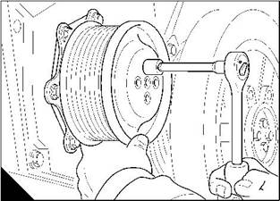
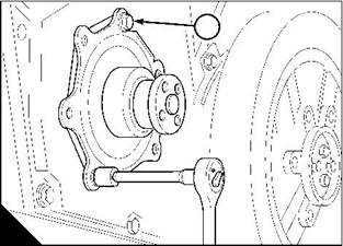
3 Remove the setscrews from the drive pulley and remove the drive pulley (A). |
|
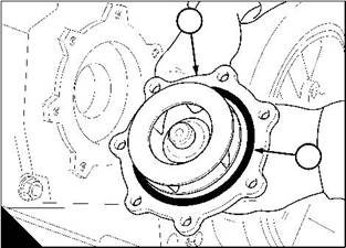
4 Remove the coolant pump fasteners (B1) and remove the coolant pump. Discard the ‘O’ ring (C2). |
|
Note: The bolt at the 1 o-clock position (B1) passes through the timing case to a nut on the rear of the timing case. |
|
1 |
|
A |
|
B |
|
W105 |
|
W106 |
|
To fit |
|
1 Ensure that the joint faces are clean. |
|
2 Fit a new ’O’ ring (C2) to the coolant pump (C1) and put the coolant pump into position. Fit the nut and bolt (B1) at the 1 o-clock position and tighten finger tight only. Fit the remaining setscrews and tighten finger tight only. Tighten all the fasteners evenly and gradually to 7 Nm (5.5 lbf ft) 0,8 kgf m. |
|
3 Fit the drive pulley and tighten the setscrews to 7 Nm (5.5 lbf ft) 0,8 kgf m (A). 4 Fit the drive belt, see Operation 12-7. |
|
5 Fill the cooling system to the correct level. |
|
1 |
|
2 |
|
C |
|
W107 |
|
Workshop Manual, TPD 1353E, Issue 3 |
|
183 |
|
This document has been printed from SPI². Not for Resale |
![]()
![]()
![]()
![]()
|
12 |
|
Peregrine EDi and 1300 Series EDi |
|
Fan |
|
To remove and to fit |
|
Operation 12-5 |
|
To remove |
|
1 Remove the fan drive belt, see Operation 12-7. 2 Release the setscrews and remove the fan. |
|
To fit |
|
1 Clean thoroughly the rear of the fan where it fits onto the fan spacer. Also ensure that all paint is removed from this area. Clean the front face of the fan spacer. Fit the fan and tighten the setscrews. |
|
2 Fit the fan drive belt, see Operation 12-7. |
|
Note: There is no need to check the tension of the belt as the tension is set automatically. |
|
Fan drive |
|
To remove and to fit |
|
Operation 12-6 |
|
To remove |
|
1 Remove the fan, see Operation 12-5. |
|
2 Release the setscrews and remove the fan spacer. Remove the drive pulley, if one is fitted, remove the fan pulley. |
|
3 Release the setscrews and remove the fan drive. |
|
4 Visually inspect the fan drive assembly for damage and wear. If the fan drive is damaged or worn it must be renewed as a unit. |
|
To fit |
|
1 Put the fan drive in position, fit and tighten the setscrews to 22 Nm (16 lbf ft) 2,2 kgf m. 2 Put the fan pulley, the drive pulley and the fan spacer in position, fit and tighten the setscrews. 3 Fit the fan, see Operation 12-5. |
|
184 |
|
Workshop Manual, TPD 1353E, Issue 3 |
|
This document has been printed from SPI². Not for Resale |
![]()
![]()
![]()
![]()
![]()
![]()
|
12 |
|
Peregrine EDi and 1300 Series EDi |
|
Fan drive belt |
|
To remove and to fit |
|
Operation 12-7 |
|
To remove |
|
Note: There is no need to check the tension of the belt as the tension is set automatically. |
|
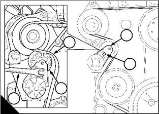
1 Fit a square headed lever (A3) into the 12,7 mm (0.5 in) hole (A2) in the fan tensioner assembly (A1). |
|
2 Operate the lever to release the tension from the belt (A4) and remove the belt. The tensioner will return to its original position by spring pressure. Remove the lever. |
|
To fit |
|
1 With the lever in the fan tensioner, pull the tensioner outwards. |
|
2 Put the fan belt in position around all of the pulleys. Ensure that the tensioner pulley (A5) is on the outside of the belt. Allow the tensioner to return and tension the belt. Remove the lever. |
|
1 |
|
4 |
|
2 |
|
5 |
|
3 |
|
A |
|
W008 |
|
Workshop Manual, TPD 1353E, Issue 3 |
|
185 |
|
This document has been printed from SPI². Not for Resale |
![]()
![]()
![]()
![]()
|
This page is intentionally blank |
|
This document has been printed from SPI². Not for Resale |
|
Peregrine EDi and 1300 Series EDi |
|
13 |
|
Flywheel and housing |
|
13 |
|
General description |
|
The steel flywheel is fitted with a hardened starter ring. The flywheel housing is made of cast iron. |
|
Workshop Manual, TPD 1353E, Issue 3 |
|
187 |
|
This document has been printed from SPI². Not for Resale |
![]()
![]()
|
13 |
|
Peregrine EDi and 1300 Series EDi |
|
Flywheel |
|
To remove |
|
Operation 13-1 |
|
Warning! The flywheel weighs 27 kg (59.5 lbs). Use lift equipment or obtain assistance to lift the flywheel. Caution: When the flywheel is removed or fitted, be careful not to damage the rear oil seal. |
|
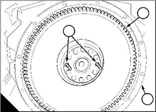
1 Remove two opposite setscrews from the flywheel (A2) and fit temporarily two guide studs (A1) to ensure safety when the flywheel is removed and fitted. |
|
2 Remove the remaining setscrews and slide the flywheel out of the flywheel housing (A3). |
|
2 |
|
1 |
|
3 |
|
A |
|
W071 |
|
188 |
|
Workshop Manual, TPD 1353E, Issue 3 |
|
This document has been printed from SPI². Not for Resale |
![]()
![]()
![]()
![]()
|
13 |
|
Peregrine EDi and 1300 Series EDi To fit |
|
Operation 13-2 |
|
1 Ensure that the location faces of the crankshaft and the flywheel are clean and free from damage. 2 Fit the flywheel over the guide studs (A1) and slide the flywheel into position. |
|
3 Fit two opposite setscrews and tighten to finger tight only. Remove the two guide studs. 4 Fit the remaining setscrews and tighten all the setscrews to 136 Nm (100 lbf ft) 13,8 kgf m. |
|
5 Check the alignment of the flywheel (B1) with a dial test indicator (B2) at a radius of 178 mm (7.0 in). Ensure that the crankshaft is pushed fully toward the front of the engine for each measurement. |
|
The maximum tolerance is given in the relevant Data and dimensions for the "Flywheel and housing" on page 18. |
|
1 |
|
1 |
|
2 |
|
A |
|
B |
|
W072 |
|
W075 |
|
Workshop Manual, TPD 1353E, Issue 3 |
|
189 |
|
This document has been printed from SPI². Not for Resale |
