
強鹿柴油發動機氣缸體的檢查和維修技術規范
詳細描述
強鹿柴油發動機氣缸體的檢查和維修技術規范
Before inspecting and cleaning cylinder block, remove allof the following:
· piston cooling orifices (A) (see REMOVE, INSPECTAND INSTALL PISTON COOLING ORIFICES later inthis group)
· soft plugs (B)
· oil gallery plugs (C) (using JDG782A Oil Gallery PlugTool)
· all external and internal mounted components (refer tothe proper group for removal procedures)
IMPORTANT: If block is cleaned in a hot tank, be sureto remove any aluminum parts such asnameplates (D). Aluminum parts can bedamaged or destroyed by hot tanksolutions.
1. Clean block thoroughly using cleaning solvent,pressure steam, or a hot tank.
2. All passages and crevices must be clear of sludge, andgrease.
3. All coolant passages must be clear of lime depositsand scale.
A—Piston Cooling Orifice
B—Soft Plug
C—Oil Gallery Plug
D—Nameplate

IMPORTANT: DO NOT file liner support flange excessively. Excess filing can damage liner support flange and allow an improper liner fit. Thoroughly clean all filings from cylinder block.
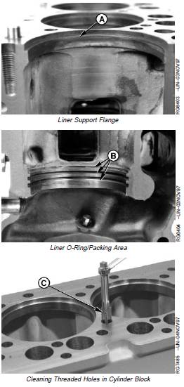
4. Inspect liner support flange (A) for burrs. If burrs are present, use a small half-moon file and LIGHTLY file (in a circular motion) burr off at a 60° angle. DO NOT let file hit top of cylinder block while filing.
5. Carefully inspect block for cracks or damage. If a cracked block is suspected, pressure-test the block. A procedure for pressure testing is outlined in FOS (Fundamentals of Service) Manual—ENGINES. Check for erosion or cracks in the liner O-ring/packing area (B). Replace cracked or damaged blocks.
6. If cylinder block is serviceable, clean out all threaded holes for cylinder head mounting cap screws in top deck of cylinder block, using JDG680 Tap (C) or an equivalent 1/2-13 UNC-2A x 76 mm (3.0 in.) long tap. Remove debris or fluid from tapped holes with compressed air.
7. After service of cylinder block, reinstall piston cooling orifices. (See REMOVE, INSPECT AND INSTALL PISTON COOLING ORIFICES later in this group.)
A—Liner Support Flange
B—O-Ring/Packing Area
C—JDG680 Tap

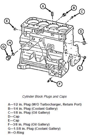
8. Apply LOCTITEâ 277 to steel caps/soft plugs and install caps in block.
9. Apply LOCTITEâ 242 Thread Lock and Sealer (Medium Strenght) to oil gallery plugs. Install plugs and tighten to specifications below.
10. Apply LOCTITEâ 592 Pipe Sealant with TEFLONâ to coolant gallery plugs. Install plugs and tighten to specifications.
Cylinder Block Oil and Coolant Gallery Plugs—Specification
1/2 in. Plug (W/O Turbocharger,
Return Port)—Torque...................................................... 45 N•m (33 lb-ft)
1/4 in. Plug (Coolant Gallery)—
Torque ............................................................................. 17 N•m (13 lb-ft)
1/8 in. Plug (Oil Gallery)—Torque................................... 17 N•m (13 lb-ft)
3/8 in. Plug (Oil Gallery)—Torque................................... 45 N•m (33 lb-ft)
1-5/8 in. Steel Plug (Coolant
Gallery)1—Torque ............................................................ 60 N•M (44 lb-ft)
1-5/8 in. Composite Plug (Coolant
Gallery)2—Torque ............................................................ 30 N•m (22 lb-ft)
1-5/8 in. Steel Square Socket
Head Plug (Coolant Gallery)—
Torque ............................................................................. 35 N•m (26 lb-ft)
LOCTITE is a registered trademark of Loctite Corp. TEFLON is a registered trademark of Du Pont Co.
1 (Saran “CD” engines S.N. —540458)
2 (Saran “CD” engines S.N. 540459—)

