
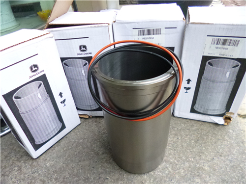
強鹿柴油機氣缸套和缸體孔的測量與標準值參數
詳細描述
John Deere約翰迪爾強鹿柴油機氣缸套和缸體孔的測量與標準值參數
Measure cylinder liners and block bores. Replace liners
not within specifications.
Specification
Lower Block Bore for Seating
Liner—ID 115.75—115.80 mm (4.557—4.559 in.)
Upper Block Bore for Seating
Liner—ID 120.70—120.75 mm (4.752—4.754 in.)
Liner Flange in Block—ID 126.33—126.35 mm (4.973—4.974 in.)
Liner at Upper Bore—OD 120.61—120.69 mm (4.7484—4.7516 in.)
Liner-to-Cylinder Block—
Clearance at Lower Bore 0.035—0.100 mm (0.001—0.004 in.)
Liner-to-Cylinder Block—
Clearance at Upper Bore 0.10—0.14 mm (0.004—0.005 in.)
Cylinder Liner—ID 106.48—106.52 mm (4.192—4.194 in.)
Cylinder—Maximum Wear.......................................... 0.10 mm (0.004 in.)
Cylinder—Maximum Taper......................................... 0.05 mm (0.002 in.)
Cylinder—Maximum
Out-of-Round.............................................................. 0.05 mm (0.002 in.)
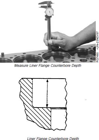
John Deere約翰迪爾強鹿柴油機缸套凸緣沉孔深度與缸套法蘭厚度的測量與標準值參數
Measure liner flange counterbore depth in block and compare to specification given below. If depth is not within specification, liner shims are available.
Specification
Cylinder Liner Flange
Counterbore—Depth in Block 5.952—5.988 mm (0.2343—0.2357 in.)
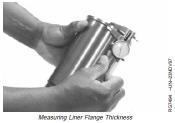
Measure cylinder liner flange thickness at several locations. If liner flange is not within specifications, liner shims are available or replace piston and liner set.
Specification
Cylinder Liner Flange—Thickness 6.022—6.058 mm (0.2371—0.2385 in.)
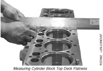
John Deere約翰迪爾強鹿柴油機氣缸體頂面平整度的測量與標準值參數
When cylinder block top deck or main
bearing bores are machined, thedimension from crankshaft centerline totop deck will be changed. Make sure
this dimension is within specifications,otherwise piston may contact cylinderhead.
Measure cylinder block top deck flatness using D05012STPrecision Straightedge and feeler gauge. If flatness is not
as specified, clean up top deck of cylinder block.
Cylinder Block Top Deck—Specification
Maximum Acceptable Out-of-Flat,
Entire Length or Width (Used)—
Measurement.............................................................. 0.08 mm (0.003 in.)
Maximum Acceptable Out-of-Flat
(Any 150 mm [5.90 in.] Length)—
Measurement............................................................ 0.025 mm (0.001 in.)
Top Deck (Surface Grind Only)
(AA)—Surface Finish 0.8—3.2 micrometers(32—125 micro-in.)
Top Deck Surface Finish—
Maximum Wave Depth........................................... 0.012 mm (0.0005 in.)
Main Bearing Bore
Centerline-to-Cylinder Block TopDeck—Distance 337.896—337.972 mm(13.3029—13.3059 in.)
氣缸套的安裝方法與標準值參數
IMPORTANT: There are different manufacturers/part numbers for piston and liner sets.These sets are notinterchangeable. DO
NOT intermix piston/liner sets on the same engine. Check parts catalog for correct applications.
IMPORTANT: Install cylinder liners into same cylinder block bore as removed. DO NOT scuff the liner packing across the uppercounterbore. or eroded liners that meet reuseguidelines should be rotated 90° from
their removed position. (See VISUALLY INSPECT CYLINDER LINERS earlier inthis group for reuse guidelines.)
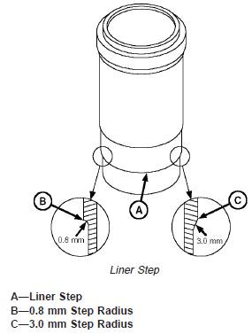
Early liners were machined with an 0.8 mm step radius which could cause damage to seals during liner installation. On these liners, blunt the sharp edge (B) of step to a 45° chamfer with a honing stone or emery cloth.
Newer liners have a 3.0 mm step radius (C) allowing for installation of linerswithout damage to seals.
1. Install liner in block bore with mark (made during disassembly) toward front of engine, unless liner OD is pitted or eroded.
If liner OD is pitted or eroded, but still within acceptable service limits, rotate liner 90° from its removed position. Pitted sections of the liner should be facing the front or rear of engine.
NOTE: Using KCD10001 (A) or JDG1145 Cylinder LinerPuller is the preferred method for seating cylinderliners.
2. A resistance will be felt when cylinder liner is aligned inpilot bore. Finish seating liners using KCD10001 (A) or
JDG1145 Cylinder Liner Puller.
A clean, hardwood block and mallet may be used if puller is not available. Gently tap hardwood block over top of cylinder liner with mallet.
NOTE: Cylinder liner will protrude over top of cylinder block more than normal due to uncompressed packings and O-rings.
IMPORTANT: If you suspect a packing may have sheared or been displaced during liner installation, remove and examine the liner and packing assembly. If no damage is found, check packings for proper position. Resoap packings andreinstall liner assembly.
3. Hold liners in place with large flat washers and cap screws. Turn cap screws snug but do not tighten.
4. Clean cylinder liner bores with waterless hand cleaner after installation. Wipe dry with clean towels.
5. Apply clean engine oil to liner bores immediately to prevent corrosion.

