強鹿柴油機正時齒輪蓋的拆卸規范與方法
詳細描述
John Deere約翰迪爾強鹿柴油機正時齒輪蓋的拆卸規范與方法
NOTE: It is not necessary to remove belt tensioner(two-valve head engines and some four-valvehead engines), water pump pulley or water pumpwhen removing timing gear cover.
IMPORTANT: Whenever the aluminum timing gearcover or water pump are replaced, thecooling system should be flushed andserviced. See FLUSH AND SERVICECOOLING SYSTEM in Section 01, Group002. Ensure system, including radiator,is completely drained.
1. Drain oil from engine crankcase.
2. Remove fan.
3. Remove oil pan.
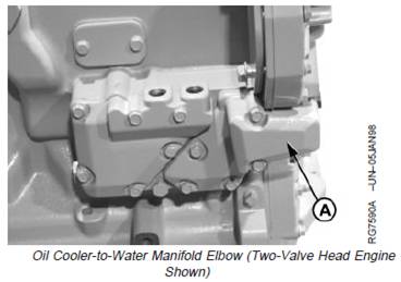
4. Remove oil cooler-to-water manifold elbow (A) at frontplate.
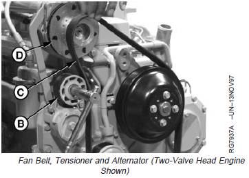
5. Release fan belt tensioner (B) and remove fan belt (C).
6. On Four-Valve Head Engines: If needed remove fanbelt tensioner and bracket as an assembly.
7. Remove alternator (D) and alternator mounting bracket.(See REMOVE AND INSTALL ALTERNATOR in Group100.)
8. On non-auxiliary drive engines, remove tensionerbracket.
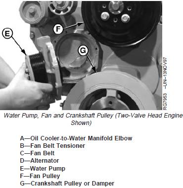
9. Remove water pump (E), if desired. (See REMOVEWATER PUMP in Group 070.)
10. Remove fan pulley (F).
11. Remove crankshaft pulley or damper (G). (SeeREMOVE PULLEY OR VIBRATION DAMPER ANDPULLEY in Group 040.)
12. Remove unitized front oil seal/wear sleeve, ifequipped. (See REPLACE FRONT CRANKSHAFTOIL SEAL AND WEAR SLEEVE in Group 040.)
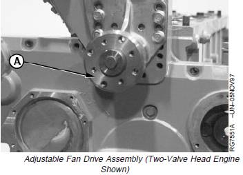
13. Remove adjustable fan drive assembly (A). (SeeREMOVE AND INSPECT FAN DRIVE ASSEMBLY inGroup 070.)
A—Adjustable Fan Drive
14. On Two-Valve Head Engines: unscrew oil pressureregulating valve plug, if required. Remove spring andvalve. (See REMOVE AND INSTALL OIL PRESSUREREGULATING VALVE in Group 060.)
15. Remove auxiliary drive cover and gears, if equipped,as described later in this group. (See REMOVE ANDINSTALL CAMSHAFT GEAR-DRIVEN AUXILIARYDRIVE later in this group.)

NOTE: Mark and identify location of timing gear coverhardware before removal to aid in reassembly.
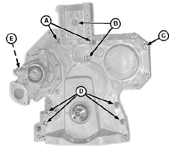
16. On Later, Two-Valve Head Engines:1 remove timinggear cover-to-cylinder block stud nuts and washers(A).
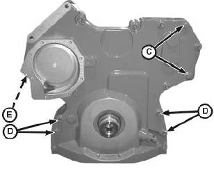
17. On All Engines: remove timing gear cover-to-cylinderblock stud nuts and washers (D).
18. On Two-Valve Head Engines: remove cap screws(B).
19. Remove cap screws (C) bordering timing cover andcap screw (E) on back of engine front plate. Removecover.
20. Remove two piece oil seal/wear sleeve, if equipped.(See REPLACE FRONT CRANKSHAFT OIL SEALAND WEAR SLEEVE in Group 040.)
A—Stud Nuts and Washers
B—Cap Screws
C—Cap Screws
D—Stud Nuts and Washers
E—Cap Screw (Behind Engine Front Plate)
